


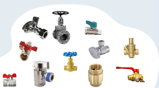
Accurate flow regulation is essential for maintaining efficiency, safety, and product quality in industrial processes. Manufacturing plants, chemical facilities, power stations, water treatment systems, and other process industries rely on equipment that can adjust the movement of liquids, gases, and steam according to changing operating requirements. A control valve plays a central role in these systems by regulating flow in response to signals from an automated control system or a manual operator.
Unlike simple isolation valves, which are primarily designed to start or stop flow, control valves are intended to adjust process conditions continuously or in defined increments. Understanding their operating principles, available designs, and selection requirements helps engineers develop reliable piping and process control systems. Choosing an appropriate Control Valve also requires considering the fluid, pressure conditions, required control range, and compatibility with the actuator and control equipment.
What Is a Control Valve?
A control valve is a mechanical device used to regulate the flow, pressure, temperature, or liquid level within a process system. It changes the size of the flow passage in response to a control signal, allowing the process variable to remain near a desired setpoint.
Control valves are commonly used as final control elements in automated systems. A typical installation includes:
- Valve body: Contains the flow passage and internal components.
- Trim: Includes the plug, disc, seat, cage, or other parts that influence flow.
- Actuator: Supplies the force needed to move the valve.
- Positioner: Helps position the valve according to the control signal.
- Controller: Compares measured process conditions with the setpoint and sends an appropriate command.
Not every control valve installation uses a separate positioner, but it is common in applications requiring accurate positioning or improved response.
How Does a Control Valve Work?
A control valve operates by changing its opening in response to a signal from a process control system. The controller monitors a variable such as flow rate, pressure, temperature, or liquid level and compares the measurement with the required setpoint.
When a difference occurs, the controller sends a signal to the valve actuator. The actuator moves the valve stem or shaft, adjusting the position of the internal closing element and changing the available flow area.
1. Process Measurement
A sensor or transmitter measures the relevant process variable. For example, a flow transmitter may measure the amount of liquid passing through a pipeline.
2. Signal Processing
The controller compares the measured value with the desired setpoint. It calculates the adjustment needed to reduce the difference between them.
3. Actuator Movement
The controller sends a command to the actuator. Depending on the system, this may be a pneumatic, electrical, hydraulic, or digital signal.
4. Flow Adjustment
The actuator moves the valve trim, increasing or decreasing the opening. This changes the flow rate and influences the process variable.
5. Continuous Correction
The measurement and adjustment process continues while the system operates. This feedback loop helps maintain the required process conditions despite changing demand or disturbances.
Main Functions of Control Valves in Industrial Systems
Control valves perform several important functions across industrial processes. Their specific role depends on the process design and the variable being regulated.
Flow Rate Regulation
One of the most common functions is controlling the amount of fluid passing through a pipeline.
By adjusting the valve opening, the system can increase or decrease flow according to production requirements. This is particularly important in chemical dosing, water distribution, cooling systems, and material processing.
Pressure Control
Control valves can maintain pressure at a required level by adjusting flow through a process line.
For example, a pressure-reducing control valve may regulate downstream pressure when upstream pressure varies. Other control arrangements regulate upstream pressure by adjusting the amount of fluid discharged.
Temperature Regulation
Temperature control systems often use valves to regulate the flow of heating or cooling media.
In a heat exchanger, for instance, a control valve may adjust the flow of steam, hot water, or cooling water to maintain the required outlet temperature.
Liquid Level Control
In tanks, separators, and process vessels, control valves can regulate inlet or outlet flow to maintain a target liquid level.
A level transmitter sends measurements to the controller, which adjusts the valve position as needed.
Process Stability
Variations in flow, pressure, and temperature can affect product quality and equipment performance. Properly selected and tuned control valves help reduce these fluctuations and support consistent process operation.
Common Types of Control Valves
Different valve designs offer different flow characteristics, pressure capabilities, and control performance. Selecting the right type depends on the service conditions and required degree of regulation.
1. Globe Control Valves
Globe control valves use a movable plug or disc that changes the opening between the plug and seat.
<AsyncImage query=”industrial globe control valve cutaway sectional technical illustration” aspectRatio=”16:9″ width=”100%”/>
Their internal design supports controlled changes in flow area and is widely used in applications requiring accurate throttling.
Advantages:
- Available with a range of flow characteristics.
- Suitable for many pressure and temperature conditions.
- Can provide effective throttling performance.
- Available with specialized trim for demanding services.
Limitations:
- Pressure drop can be relatively high.
- Larger sizes may require substantial actuator force.
- Internal trim may experience wear in erosive or cavitating service.
Globe control valves are commonly used in chemical processing, steam systems, power generation, and industrial utilities.
2. Ball Control Valves
Ball control valves use a rotating ball with a shaped or specially designed flow passage. The ball changes the available flow area as it rotates.
<AsyncImage query=”industrial characterized V port ball control valve sectional diagram” aspectRatio=”16:9″ width=”100%”/>
Standard full-port ball valves are primarily intended for isolation. For control applications, characterized designs such as V-port ball valves are often used because their geometry can provide more predictable throttling behavior.
Advantages:
- Quarter-turn operation.
- Compact configurations are available.
- Suitable designs can provide useful control characteristics.
- Can handle a range of industrial fluids.
Limitations:
- Standard on/off ball valves may not provide suitable throttling performance.
- Seat and ball wear can affect control accuracy.
- Cavitation and erosion must be considered in demanding services.
V-port ball valves are used in applications involving liquid, gas, and process flow regulation when their design and sizing are appropriate.
3. Butterfly Control Valves
Butterfly control valves regulate flow through a rotating disc positioned inside the pipeline.
<AsyncImage query=”industrial butterfly control valve cutaway disc actuator illustration” aspectRatio=”16:9″ width=”100%”/>
The disc rotates to change the available flow passage. Specialized butterfly valve designs and trim arrangements can provide suitable control characteristics across a range of operating conditions.
Advantages:
- Compact construction.
- Relatively low weight compared with some larger valve designs.
- Suitable for large pipeline diameters.
- Quarter-turn actuation.
Limitations:
- Control performance depends strongly on disc design and sizing.
- Available rangeability may be more limited than some globe valve designs.
- High pressure drops and unsuitable operating points can cause vibration or cavitation.
Butterfly control valves are commonly considered for water treatment, HVAC, cooling water, and large-volume industrial flow systems.
4. Diaphragm Control Valves
Diaphragm control valves use a flexible diaphragm to regulate or isolate fluid flow. The diaphragm moves toward or away from a seating surface in response to actuator movement.
<AsyncImage query=”industrial diaphragm control valve sectional cutaway diagram” aspectRatio=”16:9″ width=”100%”/>
These valves can be useful where minimizing contact between the process fluid and certain valve components is important.
Advantages:
- Can provide a relatively isolated flow path.
- Suitable designs are available for corrosive fluids.
- Some configurations are useful in hygienic applications.
- Can handle selected fluids containing suspended solids.
Limitations:
- Diaphragm materials have defined pressure and temperature limits.
- Flexible components require periodic inspection.
- Not every design is suitable for high-pressure service.
Diaphragm control valves are used in chemical processing, water treatment, pharmaceutical manufacturing, and selected food processing systems.
5. Pinch Control Valves
Pinch valves regulate flow by compressing a flexible sleeve inside the valve body.
<AsyncImage query=”industrial pneumatic pinch control valve sleeve cutaway technical diagram” aspectRatio=”16:9″ width=”100%”/>
The actuator applies force to the sleeve, reducing or closing the flow passage. Releasing the force allows the sleeve to reopen.
Advantages:
- The process fluid primarily contacts the sleeve.
- Suitable for selected abrasive and solids-containing fluids.
- Relatively simple internal flow path.
- Can provide effective shutoff in suitable applications.
Limitations:
- Sleeve material must match the fluid and operating temperature.
- Sleeve wear may limit service life.
- Pressure and vacuum capabilities vary by construction.
Pinch control valves are commonly used in mining, wastewater treatment, slurry handling, and bulk material processing.
Types of Control Valve Actuators
An actuator converts a control signal or energy source into mechanical movement. Its selection influences valve response, positioning accuracy, operating force, and maintenance requirements.
Pneumatic Actuators
Pneumatic actuators use compressed air to move the valve.
They are widely used in industrial environments because they can provide relatively fast operation and are available in spring-return and double-acting configurations.
Common benefits include:
- Simple and robust construction.
- Suitable operating force for many industrial valves.
- Spring-return options for defined failure positions.
- Broad use in automated process systems.
The availability and quality of instrument air must be considered during system design.
Electric Actuators
Electric actuators use an electric motor and mechanical transmission to position the valve.
They are useful where compressed air is unavailable or where electrical control and feedback are preferred.
Common benefits include:
- Precise positioning with suitable control equipment.
- No requirement for instrument air.
- Integration with digital control systems.
- Availability of local and remote operating functions.
Electrical supply, enclosure protection, duty cycle, and environmental conditions should be checked before selection.
Hydraulic Actuators
Hydraulic actuators use pressurized fluid to produce movement.
They can deliver high operating forces and are used in applications involving large valves or demanding pressure conditions.
Common benefits include:
- High force output.
- Suitability for large valve assemblies.
- Controlled movement with suitable hydraulic systems.
Hydraulic power units, fluid condition, leakage prevention, and maintenance requirements must be considered.
Understanding Control Valve Flow Characteristics
Flow characteristics describe how the flow rate changes as the valve moves through its operating range. They are important when selecting a valve for a specific control loop.
Linear Flow Characteristic
In an ideal linear characteristic, equal changes in valve travel produce approximately equal changes in flow coefficient under specified test conditions.
This characteristic may be suitable for applications where the pressure drop across the valve remains relatively stable.
Equal Percentage Flow Characteristic
With an equal percentage characteristic, equal increments of valve travel produce approximately equal percentage changes in flow coefficient.
This behavior is commonly used where the pressure drop across the valve changes as the system flow changes.
Quick Opening Characteristic
A quick opening valve produces a relatively large increase in flow with a small initial movement.
It is generally more suitable for rapid flow delivery or on/off duties than for precise regulation across the full operating range.
The installed flow characteristic may differ from the inherent characteristic because pipeline pressure losses and changing process conditions influence actual valve performance.
Important Factors When Selecting a Control Valve
A control valve must be matched to the process rather than selected solely by pipeline diameter or connection type.
1. Fluid Properties
Identify the fluid being handled and evaluate its:
- Density and viscosity.
- Chemical composition.
- Temperature.
- Vapor pressure.
- Presence of suspended solids.
- Potential for corrosion or erosion.
These properties influence valve body materials, trim selection, sealing components, and overall design.
2. Operating Pressure and Temperature
Review normal, minimum, and maximum operating conditions.
The valve body, bonnet, trim, packing, and seals must all be suitable for the expected pressure and temperature range. Ratings may vary with material and design.
3. Required Flow Capacity
Valve sizing should account for minimum, normal, and maximum flow rates.
An oversized valve may operate close to its seat during normal conditions, making stable regulation difficult. An undersized valve may restrict the required maximum flow or create excessive pressure loss.
Engineers commonly use flow coefficient data, such as Cv or Kv, to evaluate capacity.
4. Pressure Drop
Determine the pressure available across the valve under different operating conditions.
Excessive pressure drop can contribute to noise, vibration, cavitation in liquids, or high gas velocities. The valve must be evaluated for the full range of expected conditions.
5. Rangeability
Rangeability describes the ratio between the maximum controllable flow and the minimum controllable flow under specified conditions.
Applications with large variations in demand may require a valve with suitable rangeability and stable performance at low flow rates.
6. Actuator and Failure Position
Choose an actuator capable of supplying the required force or torque throughout the operating range.
Also determine the required failure position. Depending on the process safety assessment, the valve may need to move to a fail-open, fail-closed, or fail-in-place condition if its power or control signal is lost.
7. Control System Compatibility
Confirm that the valve actuator and positioner are compatible with the plant’s control architecture.
This includes signal type, communication protocol, feedback requirements, response time, and available power or instrument air.
Control Valves vs. Isolation Valves
Control valves and isolation valves may look similar, but their intended duties are different.
| Feature | Control valve | Isolation valve |
|---|---|---|
| Main purpose | Regulate process conditions | Start or stop flow |
| Typical operation | Modulating | Fully open or fully closed |
| Positioning | Adjusted across an operating range | Usually operated between end positions |
| Common designs | Globe, characterized ball, control butterfly | Gate, standard ball, and butterfly |
| Control system | Often connected to a controller | May be manual or automated |
A standard isolation valve should not automatically be used for continuous throttling. Operating a valve outside its intended duty can cause unstable flow, excessive wear, vibration, or damage to the seating surfaces.
Common Control Valve Problems and Their Causes
Control valve performance can deteriorate because of mechanical wear, incorrect sizing, poor installation, or control loop problems.
| Problem | Possible cause | Recommended action |
|---|---|---|
| Unstable flow | Incorrect sizing or poor control loop tuning | Review valve sizing and controller settings |
| Excessive noise | High fluid velocity, cavitation, or turbulence | Evaluate pressure drop and specialized trim |
| Valve hunting | Poor tuning, actuator issues, or process instability | Check controller settings and actuator response |
| Internal leakage | Damaged seat, plug, or sealing surfaces | Inspect and repair or replace affected components |
| Slow response | Actuator friction or inadequate air or power supply | Inspect actuator and supply conditions |
| Stem or shaft wear | Misalignment, corrosion, or unsuitable materials | Check installation and material compatibility |
| Positioning errors | Faulty positioner or feedback signal | Calibrate and test the control equipment |
A structured diagnostic process should examine the valve, actuator, positioner, instrumentation, and control loop rather than treating every problem as a valve-body fault.
Maintenance Best Practices for Control Valves
Regular inspection and preventive maintenance help maintain control accuracy and reduce unexpected shutdowns.
Important practices include:
- Inspect the valve body, connections, and actuator for visible damage or leakage.
- Monitor unusual noise, vibration, and changes in process performance.
- Check the actuator’s air, hydraulic, or electrical supply.
- Verify positioner calibration and feedback accuracy.
- Inspect trim, packing, seals, and seating surfaces during scheduled maintenance.
- Check for deposits, corrosion, erosion, or mechanical obstruction.
- Confirm that the valve responds correctly to control signals.
- Record maintenance findings and changes in operating performance.
Maintenance intervals should be based on service severity, operating history, manufacturer recommendations, and plant reliability requirements. Before inspection or repair, isolate the equipment, depressurize the relevant section, and follow the site’s safety and lockout procedures.
The Role of Control Valves in Modern Industrial Automation
Modern process facilities increasingly integrate control valves with distributed control systems, programmable logic controllers, and digital instrumentation.
Smart positioners and diagnostic equipment can provide information about valve travel, actuator condition, friction, and other performance indicators. When integrated appropriately, these features help maintenance teams identify developing problems before they cause major process interruptions.
Digital communication also allows operators and engineers to access device information and improve troubleshooting. However, automation does not eliminate the need for correct mechanical selection, commissioning, calibration, and periodic inspection.
Conclusion
Control valves are essential components in industrial systems that require accurate regulation of flow, pressure, temperature, or liquid level. By adjusting the flow passage in response to control signals, they help maintain stable process conditions, support product consistency, and improve operational efficiency.
Globe, characterized ball, butterfly, diaphragm, and pinch valves each offer different advantages and limitations. The right selection depends on fluid properties, pressure and temperature conditions, flow capacity, pressure drop, rangeability, actuator requirements, and the intended control strategy.
Combining appropriate valve sizing with compatible actuation, reliable instrumentation, and regular maintenance helps ensure consistent performance throughout the operating life of a process system.