


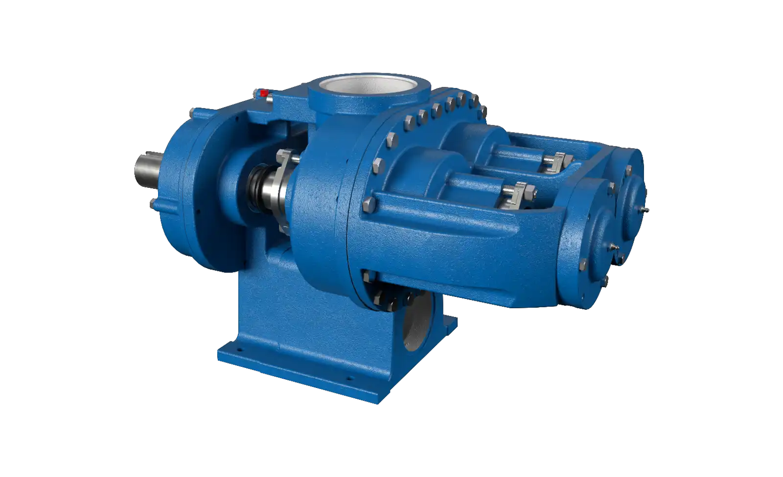
Gear pumps are widely used in hydraulic systems, lubrication equipment, fluid-transfer machinery, and industrial processing applications. Their relatively simple positive displacement principle depends on precisely manufactured components working together under controlled conditions. For this reason, the design, production, and testing processes behind a pump can have a significant effect on its reliability and performance.
When evaluating a supplier, understanding how a gear pump manufacturer approaches the complete manufacturing process can help buyers make more informed decisions. Design engineering, material selection, precision machining, assembly, inspection, and performance testing should all work together to produce a pump suited to its intended application.
Starting With Application Requirements
Gear pump development normally begins with a clear understanding of the intended operating environment. A pump cannot be properly designed without knowing how it will be used.
Key requirements may include:
- Required flow rate
- Operating pressure
- Rotational speed
- Fluid type and viscosity
- Operating temperature
- Installation dimensions
- Drive configuration
- Expected operating hours
These factors provide the foundation for selecting the appropriate pump architecture and component specifications.
Gear Pump Design Process
The design stage translates application requirements into specific mechanical characteristics. Engineers determine the pump’s displacement, gear dimensions, housing configuration, shaft arrangement, sealing system, and other critical features.
The design must balance flow requirements with mechanical strength, efficiency, heat generation, internal leakage, and service life.
Computer-aided design tools can help engineers develop and review component geometry before manufacturing begins.
Selecting the Pump Configuration
Gear pumps are available in different configurations, with external and internal gear designs serving different application requirements.
External gear pumps generally use two externally toothed gears to transfer fluid through the pump. Internal gear pumps use an inner and outer gear arrangement and can provide different operating characteristics.
The appropriate configuration depends on factors such as fluid properties, flow requirements, pressure, speed, space limitations, and application priorities.
Determining Displacement
Pump displacement represents the theoretical amount of fluid moved per revolution. Engineers use displacement and operating speed to establish the expected theoretical flow.
The actual output can be lower because of internal leakage and other operating losses.
Displacement should therefore be selected according to the desired operating range rather than simply the maximum possible flow.
Material Selection
Materials are selected according to mechanical and environmental requirements. Common options may include cast iron, aluminum, stainless steel, bronze, steel, and specialized alloys.
The gears and shafts may require materials with appropriate strength and wear resistance, while housing materials must withstand the expected pressure and fluid exposure.
Seal materials also require careful consideration because chemical compatibility and temperature resistance can affect service life.
Engineering Internal Clearances
Internal clearances are among the most important design parameters in a gear pump. The spaces between gears and surrounding surfaces must be controlled carefully.
Large clearances can increase internal leakage and reduce volumetric efficiency. Excessively tight clearances can increase friction and create the risk of component interference.
The appropriate clearance depends on factors such as pressure, viscosity, temperature, speed, and material characteristics.
Manufacturing the Components
Once the design is approved, individual components enter production. Precision machining is used to create the required dimensions and surface characteristics.
Typical components include:
- Gears
- Pump housing
- Shafts
- Bearings or bushings
- Covers and mounting components
- Seals and gaskets
Each component must meet its relevant specifications before entering the assembly process.
Gear Manufacturing
Gear production requires particular attention because gear geometry directly affects fluid displacement and mechanical operation.
Manufacturing may involve gear cutting, shaping, grinding, finishing, and inspection depending on the design and required precision.
The finished gears should have suitable tooth profiles, dimensions, surface quality, and alignment characteristics.
Shaft Manufacturing
The shaft transfers mechanical power to the pumping elements. It must withstand torque while maintaining accurate alignment during operation.
Machining accuracy is important around bearing and sealing areas. Surface finish and dimensional control can influence component wear and sealing performance.
For demanding applications, appropriate material selection and heat treatment may also be considered.
Housing Production
The housing surrounds the gears and provides the primary fluid path. Its internal dimensions must be manufactured accurately to maintain the intended clearances.
Machining may include the creation of gear cavities, bearing locations, ports, mounting surfaces, and sealing interfaces.
Dimensional inspection helps confirm that the housing is compatible with the other components before assembly.
In-Process Quality Inspection
Quality control should take place throughout production rather than only after final assembly.
Inspection can identify dimensional deviations, surface defects, material problems, or other issues before they affect later manufacturing stages.
Typical inspection activities may include dimensional measurement, gear verification, surface inspection, and component-specific checks.
Assembly Process
During assembly, individual components are combined according to the approved design. Proper positioning and alignment are essential for reliable operation.
Technicians may verify gear orientation, shaft alignment, bearing or bushing installation, internal clearances, seals, fasteners, and rotational movement.
Controlled assembly procedures help maintain consistency between production units.
Sealing and Leakage Control
Sealing components are installed to prevent fluid from escaping from the pump. Their compatibility with the application must be confirmed before assembly.
After assembly, leakage testing can help identify problems with seals, joints, surfaces, or other interfaces.
Effective leakage control is important for both pump performance and the cleanliness of the surrounding equipment.
Pressure Testing
Pressure testing evaluates whether the completed pump can withstand the specified operating conditions.
The test procedure may involve applying a defined pressure while monitoring for leakage, deformation, or other abnormal behavior.
Test parameters should correspond to the pump design and applicable technical requirements.
Flow Testing
Flow testing measures actual pump output under controlled conditions. Results can be compared with the expected performance for the selected speed, pressure, fluid, and temperature.
Because actual flow can change with operating conditions, testing provides useful information beyond theoretical displacement calculations.
For critical applications, buyers may request documented performance data.
Efficiency Evaluation
Pump efficiency can be influenced by volumetric leakage, mechanical friction, fluid viscosity, pressure, and speed.
Testing can help determine whether the completed pump performs within the expected efficiency range.
Efficiency should be evaluated at relevant operating points rather than relying only on a single laboratory condition.
Noise and Vibration Testing
Noise and vibration checks can provide information about the mechanical condition of a pump. Unusual levels may indicate problems involving gears, bearings, alignment, mounting, or fluid supply.
Not every application requires the same level of noise or vibration testing, but these measurements can be valuable for machinery where smooth operation is important.
Final Inspection
Before shipment, the completed pump may undergo a final inspection to verify dimensions, appearance, assembly, connections, and other specified characteristics.
Depending on the project, final documentation may include inspection records, test results, material information, or product identification.
The extent of final inspection should correspond to the pump’s application and customer requirements.
Testing According to Application
A standard factory test may not represent every real-world operating condition. Pumps used with different fluids, temperatures, pressures, or speeds can behave differently.
For specialized applications, test conditions may therefore need to reflect the expected service environment as closely as practical.
Providing accurate application data helps engineers determine appropriate test parameters.
Custom and OEM Production
OEM projects may require pumps with specific dimensions, materials, mounting arrangements, shaft configurations, or performance characteristics.
The development process can involve engineering review, prototype production, testing, customer approval, and repeat manufacturing.
Once a design is approved, maintaining controlled specifications is important for consistency across future production batches.
Importance of Documentation
Documentation connects the design and manufacturing processes. Drawings, specifications, inspection records, test results, and material information can provide a reference for production and future servicing.
Good documentation can also simplify communication between the manufacturer and equipment builder.
For customized pumps, controlled technical documentation is particularly important because small changes can affect compatibility with the host machine.
Evaluating a Manufacturer’s Process
Buyers can gain useful insight by asking how a prospective supplier manages each stage of production.
Consider asking:
- How are pump designs developed and reviewed?
- Which materials are available for different applications?
- What machining processes are used for gears and housings?
- How are critical dimensions inspected?
- What assembly controls are in place?
- Which pressure, flow, and leakage tests are performed?
- Can customized pumps be developed?
- What documentation accompanies finished products?
- How is production consistency maintained for repeat orders?
These questions help buyers evaluate the manufacturing process rather than relying only on product descriptions.
Final Thoughts
The performance of a gear pump is closely connected to the processes used to design, manufacture, assemble, and test it. Application requirements guide the initial design, while material selection and precision manufacturing determine whether components can achieve the intended characteristics.
In-process inspection, controlled assembly, pressure and flow testing, leakage checks, and final verification then help confirm that the completed pump meets its specifications. For industrial and OEM buyers, understanding these processes provides a stronger basis for evaluating suppliers and selecting gear pump equipment suited to long-term operating requirements.